Thứ Sáu, 31 tháng 3, 2017

STM8 decode NEC protocol

1. NEC protocol.

  • Chuẩn NEC


Hình 1.

       Ngõ ra mắt thu hồng ngoại sẽ bị đảo mức so với chuẩn NEC.

                 -Xung start:


Hình 2.
    • 9ms xung mức thấp.
    • 4.5ms xung mức cao.
             
       -32 bit data:
    • 8 bit địa chỉ.
    • 8 bit đảo của 8 bit địa chỉ.
    • 8 bit command.
    • 8 bit đảo của 8 bit command
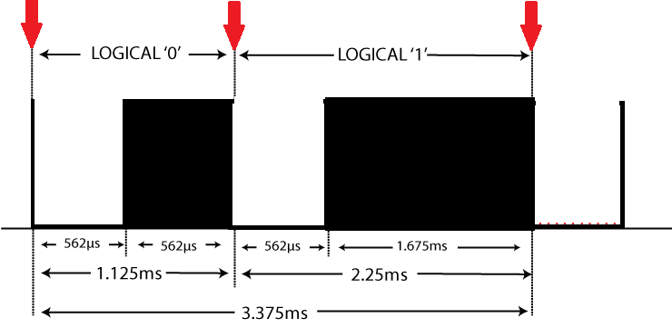
  • Xung mức logic 0 và 1


Hình 3.


    • Logical '0' – 562.5µs xung mức thấp, 562.5µs xung mức cao, tổng thời gian 1.125ms
    • Logical '1' – 562.5µs xung mức mức thấp, 1.6875ms xung mức cao, tổng thời gian 2.25ms.
  • Giải mã chuẩn NEC.

           -Sử dụng STM8S003 giải mã NEC, dùng timer ngắt 0.5 ms và ngắt port để detect xung start, 32 bit data.

           -Detect xung start: set port ngắt cạnh xuống, khi port nhảy vào ngắt kiểm tra thời gian timer đếm được ,nếu timer đếm được khoảng 13ms (9 ms + 4.5 ms) => Xung start (Vị trí ngắt màu đỏ Hình 2).

           -Detect 32 bit data: set port ngắt cạnh xuống, khi port nhảy vào ngắt kiểm tra thời gian timer đếm được (Vị trí ngắt màu đỏ Hình 3):

    • Nếu timer đếm được nhỏ hơn 2 ms (562.5µs + 562.5µs ) => Logic 0.
    • Nếu timer đếm được lớn hơn 2 ms (562.5µs + 1.6875ms ) => Logic 1.
  • Code:


Ngắt timer 0.5 ms:
INTERRUPT_HANDLER(TIM4_UPD_OVF_IRQHandler, 23)

 {

        count_ms++;

        if(count_ms==50) 

        count_ms=0;

        TIM4_ClearITPendingBit(TIM4_IT_UPDATE);

 }


 Ngắt Port:


INTERRUPT_HANDLER(EXTI_PORTB_IRQHandler, 4)
{

    if ((GPIO_ReadInputData(GPIOB) & 0x20) == 0x00)
   {
       /////
      count_ms1=count_ms;
      count_ms=0;
      count_data++;
      if(((count_ms1)>=20)&((count_ms1)<=28))//10s-14s
      {
        count_data=-1;
        start_status=1;
        count_ms1=0;
      }
      else if((start_status==1)&(count_data>=0)&(count_data<=31))
      {
          if((count_ms1>=4)&(count_ms1<=6))//2ms->3ms //detect logic 1.
          {
              data|=(uint32_t)1<<(31-count_data);
              count_ms1=0;
          }
          else if(count_ms1<4)//nho hon <2s //detect logic 0.
          {
               count_ms1=0;
           }
           else //error data reset all
           {
              count_ms1=0;
              start_status=0;
              count_data=0;
              data=0;
           }
           ////
      }
      else if((start_status=0)&((count_ms1)>28))/// error detect xung start
      {
          count_ms1=0;
          start_status=0;
          count_data=0;
          data=0;
      }
      ///
      if(count_data==32) //reset sau khi detect 32 bit data
      {
        count_data=0;
        data=0;
        start_status=0;
        count_ms1=0;
      }
      //////// 
  }
  ///////
}


2. Sơ đồ nguyên lý.


3. Sản phẩm hoàn thiện.


Sử dụng mạch nguồn AC-DC 220V-5V 750mA cấp nguồn cho mạch (hình trên)


4. Demo.


Mã command nút power trên remote: 0x00ffA25D


Mã command nút power trên app remote Toshiba: 0x02FD48B7


Mã command nút power trên app remote LG: 0x20DF10EF


Video demo:


Bổ sung.


Chỉnh sửa hardware để điều khiển được bóng đèn huỳnh quang, lý do khi sử dụng relay tiếp điểm để điều khiển đèn huỳnh quang gây nhiễu khi đèn khởi động ("stater" hay "chuột" khởi động tạo hồ quang điện gây nhiễu).

Ngoài ra chọn lại nguồn AC-DC 5V filter tốt hơn (mình dùng mạch sạc Travel Adapter của samsung, mạch này lọc nhiễu đầu vào tốt hơn mạch bên trên mình đã dùng). Để nguồn DC ngõ ra filter tốt hơn ,ít nhiễu hơn mình còn gắn thêm cuộn cảm 330uH nối tiếp DC ngõ ra adapter.


Thay relay tiếp điểm bằng solib state relay (SSR).


Mạch sau khi sửa.


Video demo:


8

Thứ Hai, 3 tháng 10, 2016

DIY chống trộm xe máy rev00

DIY MẠCH CHỐNG TRỘM XE MÁY CƠ BẢN REV00

1. Nguyên lý hoạt động.

  • Mạch có chức năng chống trộm bẻ khóa và tìm xe máy trong bãi giữ xe.
  • Mạch kích hoạt chế độ chống bẻ khóa và tìm xe bằng remote RF 315Mhz.
  • Chế độ hoạt động:
           - Chế độ chống bẻ khóa: còi và đèn xi nhan sẽ nháy 2 lần. kích hoạt bằng phím C trên remote.
           - Tắt chế độ chống bẻ khóa: còi và đèn xi nhan sẽ nháy 1 lần, kích hoạt bằng phím D trên remote.
           - Tìm xe trong bãi: còi và đèn xi nhan sẽ nháy 5 lần, kích hoạt bằng phím A trên remote.

2. Sơ đồ nguyên lý.


Sơ đố nguyên lý


Layout.

  • Mạch sử dụng bộ thu phát RF gồm 1 remote 4 phím 315Mhz(chip PT2262) và mạch thu PT2272-M4.


  • Mạch sử dụng chip STM8S003K6 để sử lý tín hiệu từ mạch thu RF => điều khiển còi và đèn xi nhan.


3. Sản phẩm hoàn thiện


Mạch hoàn thiện


4. Lắp vào xe máy.


B1: Cấp nguồn cho mạch: nguồn dương nối vào dây màu đỏ của xe máy, nguồn âm nối vào dây màu xanh của xe.

B2: Ngắt nguồn xe máy: cắt đôi dây đen trên ổ khóa.


Ảnh dây nối ổ khóa xe máy wave alpha.

B3: Nối dây xi nhan.


Ảnh thực tế 2 dây xinhan trái và phải trên xe wave alpha.


Mạch sau khi lắp vào xe máy.


Video demo :


Thứ Năm, 28 tháng 7, 2016

STM32 USB-HID

KHỞI TẠO USB HID STM32F103C8T6 ĐƠN GIẢN BẰNG STM32CUBEMX

1. Hardware

Kit STM32F103C8T6


Schematic kit


2. Khởi tạo STM32CubeMx

STEP 1:

Vào chương trình STM32CubeMX -> Chon Create new project. -> Chọn MCU STM32F103C8Tx( STM32F103C8T6).


STEP 2:

Trong muc Pinout.

 Peripherals => USB => Tick vào Device(FS)

 Middlewares=> Custom Human Interface Device Class(HID).


 STEP 3:

Trong mục Pinout.

Peripherals => RCC => High Speed Clock (HSE) =>Chọn => Crytal/Ceramic Resonator.


STEP 4:

Trong mục Clock configuration.

Config Clock USB => 48Mhz.


STEP 5:

Trong mục Configuration.

Trong cửa sổ chính => Connectivity => USB.


STEP 6:

Xuất hiện hôp thoại USB Configuration => Tab Parameter settings => Basic parameters =>  Endpoint 0 Max Packet size => 64 byte. (Maximum gói data endpoint 0 là 64 byte)


STEP 7: 

Trong mục Configuration.

Trong cửa sổ chính => Middlewares =>USB_DEVICE.


STEP 8:

Xuất hiện hôp thoại USB_DEVICE Configuration => Tab Parameter settings => Class parameters :
  • USBD_CUSTOM_HID_REPORT_DESC_SIZE (Total length for Report descriptor (IN ENDPOINT)): 32 (32 byte mô tả report input).
  • USBD_CUSTOMHID_OUTREPORT_BUF_SIZE (Maximum report buffer size (OUT ENDPOINT)): 64 ( maximum 64 byte buffer report output ).


STEP 9:

Xuất hiện hôp thoại USB_DEVICE Configuration => Tab Device Descriptor => Device Descriptor FS => PRODUCT_STRING (Product Identifier) =>Đổi Product string USB HID.


3. Config file mô tả USB HID (USB HID Report Descriptor).


  • Trong file usbd_custom_hid_if.c


__ALIGN_BEGIN static uint8_t CUSTOM_HID_ReportDesc_FS[USBD_CUSTOM_HID_REPORT_DESC_SIZE] __ALIGN_END =
{
  /* USER CODE BEGIN 0 */ 
  0x00, 
  /* USER CODE END 0 */ 
  0xC0    /*     END_COLLECTION             */
 
};

Sửa thành=====>

__ALIGN_BEGIN static uint8_t CUSTOM_HID_ReportDesc_FS[USBD_CUSTOM_HID_REPORT_DESC_SIZE] __ALIGN_END =
{
    0x05, 0x01,                    // USAGE_PAGE (Generic Desktop)
    0x09, 0x00,                    // USAGE (Undefined)
    0xa1, 0x01,                    // COLLECTION (Application)
    0x15, 0x00,                    //   LOGICAL_MINIMUM (0)
    0x26, 0xff, 0x00,              //   LOGICAL_MAXIMUM (255)
    0x85, 0x01,                    //   REPORT_ID (1) //report id input là 0x01
    0x75, 0x08,                    //   REPORT_SIZE (8)
    0x95, 0x3F,                    //   REPORT_COUNT (63)//report input gồm có 63 byte data và một byte ID=0x01
    0x09, 0x00,                    //   USAGE (Undefined)
    0x81, 0x82,                    //   INPUT (Data,Var,Abs,Vol) - to the host
    0x85, 0x02,                    //   REPORT_ID (2)//report id output là 0x02
    0x75, 0x08,                    //   REPORT_SIZE (8)
    0x95, 0x3F,                    //   REPORT_COUNT (63)//report output gồm có 63 byte data và một byte ID=0x02
    0x09, 0x00,                    //   USAGE (Undefined)
    0x91, 0x82,                    //   OUTPUT (Data,Var,Abs,Vol) - from the host
    0xc0                           // END_COLLECTION
};

USBD_CUSTOM_HID_REPORT_DESC_SIZE: 32 byte mô tả đã config trên soft STM32CubeMX.

  • Trong file usb_customhid.h


#define CUSTOM_HID_EPIN_ADDR                 0x81
#define CUSTOM_HID_EPIN_SIZE                 0x02

#define CUSTOM_HID_EPOUT_ADDR                0x01
#define CUSTOM_HID_EPOUT_SIZE                0x02

Sửa thành===>

#define CUSTOM_HID_EPIN_ADDR                 0x81
#define CUSTOM_HID_EPIN_SIZE                 64

#define CUSTOM_HID_EPOUT_ADDR                0x01
#define CUSTOM_HID_EPOUT_SIZE                64
///////////////////////////////

4. Send và Receive data.

  •  Send data:

uint8_t USBD_CUSTOM_HID_SendReport     (USBD_HandleTypeDef  *pdev, uint8_t *report, uint16_t len);
VD: 

uint8_t data[64];

data[0]=0x01;  //report id input là 0x01, byte đầu tiên phải là report id.

USBD_CUSTOM_HID_SendReport(&hUsbDeviceFS,data,64); 

Khi config USBD_CUSTOM_HID_REPORT_DESC_SIZE=64 thì gửi gói data luôn có len=64.

Note: Nếu muốn gửi và nhận gói data >64 byte VD 128 byte có thể sửa như sau:

USBD_CUSTOM_HID_REPORT_DESC_SIZE=128

CUSTOM_HID_ReportDesc_FS[USBD_CUSTOM_HID_REPORT_DESC_SIZE] __ALIGN_END =
{
    0x05, 0x01,                    // USAGE_PAGE (Generic Desktop)
    0x09, 0x00,                    // USAGE (Undefined)
    0xa1, 0x01,                    // COLLECTION (Application)
    0x15, 0x00,                    //   LOGICAL_MINIMUM (0)
    0x26, 0xff, 0x00,              //   LOGICAL_MAXIMUM (255)
    0x85, 0x01,                    //   REPORT_ID (1) //report id input là 0x01
    0x75, 0x08,                    //   REPORT_SIZE (8)
    0x95, 127,                    //   REPORT_COUNT (127)//report input gồm có 127 byte data và một byte ID=0x01
    0x09, 0x00,                    //   USAGE (Undefined)
    0x81, 0x82,                    //   INPUT (Data,Var,Abs,Vol) - to the host
    0x85, 0x02,                    //   REPORT_ID (2)//report id output là 0x02
    0x75, 0x08,                    //   REPORT_SIZE (8)
    0x95, 127,                    //   REPORT_COUNT (127)//report output gồm có 127 byte data và một byte ID=0x02
    0x09, 0x00,                    //   USAGE (Undefined)
    0x91, 0x82,                    //   OUTPUT (Data,Var,Abs,Vol) - from the host
    0xc0                           // END_COLLECTION
};

uint8_t data[128];

data[0]=0x01;  //report id input là 0x01, byte đầu tiên phải là report id.

USBD_CUSTOM_HID_SendReport(&hUsbDeviceFS,data,128); 

  • Receive data:

 Trong file usbd_customhid.c thêm vào phần màu đỏ:

uint8_t My_Buffer[USBD_CUSTOMHID_OUTREPORT_BUF_SIZE];

static uint8_t  USBD_CUSTOM_HID_DataOut (USBD_HandleTypeDef *pdev,
                              uint8_t epnum)
{

  USBD_CUSTOM_HID_HandleTypeDef     *hhid = (USBD_CUSTOM_HID_HandleTypeDef*)pdev->pClassData;

 ((USBD_CUSTOM_HID_ItfTypeDef *)pdev->pUserData)->OutEvent(hhid->Report_buf[0],         hhid->Report_buf[1]);
///////////////////////////////
for(uint8_t i=0;i<64;i++)
{
    My_Buffer[i]=hhid->Report_buf[i];  //gán buffer Report_buf vào My_Buffer để truy xuất data.
}
//////////////////
  USBD_LL_PrepareReceive(pdev, CUSTOM_HID_EPOUT_ADDR , hhid->Report_buf,
                         USBD_CUSTOMHID_OUTREPORT_BUF_SIZE);

  return USBD_OK;
}

5. Example code:


  •   Code nhận data và gửi data đã nhận lên máy tính. Test bằng phần mềm USB HID Demonstrator(v1.02)

  /////////////////////////////////////////////////
  uint8_t data[64];
  data[0]=0x01;
  while (1)
  {
if(check_usb==1)
{
HAL_GPIO_TogglePin(LED_GPIO_Port, LED_Pin);
for(uint8_t i=1;i<64;i++)
{
    data[i]=My_Buffer[i];
}
USBD_CUSTOM_HID_SendReport(&hUsbDeviceFS,data,64);   
check_usb=0;
}
  }
  /////////////////////////////////////////////
Link demo code:
https://drive.google.com/file/d/0B9pHWA4exz3gU3lzZDBlMWExMGM/view?usp=sharing

USB HID Demonstrator(v1.02): https://drive.google.com/file/d/0B9pHWA4exz3gNWNGak9zY1dVakU/view?usp=sharing

Video demo:

Thứ Sáu, 15 tháng 7, 2016

STEMWIN (P1)

LCD TFT ILI9325 - STEMWIN (P1)

  1. Chuẩn bị phần cứng.

  • Kit STM32F411 Nucleo.


  • LCD TFT 2.8 inch 240x320 (Driver ILI9320)


LCD TFT 2.8 inch


Sơ đồ chân LCD.


Adapter kết nối kit STM32F411 với LCD TFT.

  • Sơ đồ kết nối phần cứng.

Sơ đồ kết nối


2. Khởi tạo LCD.

//////////////////////////////////////////////////////Code//////////////////////////////////////////
void ILI9325_Init(void)
{
   Config_GPIO_LCD();
  RST_L;
  HAL_Delay(100);
  RST_H;
  HAL_Delay(100);
  CS_H;
  WR_H;
  RD_H;
  RS_H;
  /* Start Initial Sequence --------------------------------------------------*/
  ili9325_WriteReg(LCD_REG_0, 0x0001); /* Start internal OSC. */
ili9325_WriteReg(LCD_REG_1, 0x0000); /* Set SS and SM bit */
  ili9325_WriteReg(LCD_REG_2, 0x0700); /* Set 1 line inversion */
  ili9325_WriteReg(LCD_REG_3, 0x1030); /* Set GRAM write direction and BGR=1. */  
  ili9325_WriteReg(LCD_REG_4, 0x0000); /* Resize register */
/////
  ili9325_WriteReg(LCD_REG_8, 0x0207); /* Set the back porch and front porch */
  ili9325_WriteReg(LCD_REG_9, 0x0000); /* Set non-display area refresh cycle ISC[3:0] */
  ili9325_WriteReg(LCD_REG_10, 0x0000); /* FMARK function */
  ili9325_WriteReg(LCD_REG_12, 0x0000); /* RGB interface setting */
  ili9325_WriteReg(LCD_REG_13, 0x0000); /* Frame marker Position */
  ili9325_WriteReg(LCD_REG_15, 0x0000); /* RGB interface polarity */

  /* Power On sequence -------------------------------------------------------*/
  ili9325_WriteReg(LCD_REG_16, 0x0000); /* SAP, BT[3:0], AP, DSTB, SLP, STB */
  ili9325_WriteReg(LCD_REG_17, 0x0000); /* DC1[2:0], DC0[2:0], VC[2:0] */
  ili9325_WriteReg(LCD_REG_18, 0x0000); /* VREG1OUT voltage */
  ili9325_WriteReg(LCD_REG_19, 0x0000); /* VDV[4:0] for VCOM amplitude */

  ili9325_WriteReg(LCD_REG_16, 0x17B0); /* SAP, BT[3:0], AP, DSTB, SLP, STB */
  ili9325_WriteReg(LCD_REG_17, 0x0137); /* DC1[2:0], DC0[2:0], VC[2:0] */

  ili9325_WriteReg(LCD_REG_18, 0x0139); /* VREG1OUT voltage */

  ili9325_WriteReg(LCD_REG_19, 0x1d00); /* VDV[4:0] for VCOM amplitude */
  ili9325_WriteReg(LCD_REG_41, 0x0013); /* VCM[4:0] for VCOMH */

  ili9325_WriteReg(LCD_REG_32, 0x0000); /* GRAM horizontal Address */
  ili9325_WriteReg(LCD_REG_33, 0x0000); /* GRAM Vertical Address */

  /* Adjust the Gamma Curve (ILI9325) ----------------------------------------*/
  ili9325_WriteReg(LCD_REG_48, 0x0007);
  ili9325_WriteReg(LCD_REG_49, 0x0302);
  ili9325_WriteReg(LCD_REG_50, 0x0105);
  ili9325_WriteReg(LCD_REG_53, 0x0206);
  ili9325_WriteReg(LCD_REG_54, 0x0808);
  ili9325_WriteReg(LCD_REG_55, 0x0206);
  ili9325_WriteReg(LCD_REG_56, 0x0504);
  ili9325_WriteReg(LCD_REG_57, 0x0007);
  ili9325_WriteReg(LCD_REG_60, 0x0105);
  ili9325_WriteReg(LCD_REG_61, 0x0808);
  /* Set GRAM area -----------------------------------------------------------*/
  ili9325_WriteReg(LCD_REG_80, 0x0000); /* Horizontal GRAM Start Address */
  ili9325_WriteReg(LCD_REG_81, 0x00EF); /* Horizontal GRAM End Address */
  ili9325_WriteReg(LCD_REG_82, 0x0000); /* Vertical GRAM Start Address */
  ili9325_WriteReg(LCD_REG_83, 0x0013F); /* Vertical GRAM End Address */

  ili9325_WriteReg(LCD_REG_96,  0x2700); /* Gate Scan Line(GS=1, scan direction is G320~G1) */
  ili9325_WriteReg(LCD_REG_97,  0x0001); /* NDL,VLE, REV */
  ili9325_WriteReg(LCD_REG_106, 0x0000); /* set scrolling line */

  /* Partial Display Control -------------------------------------------------*/
  ili9325_WriteReg(LCD_REG_128, 0x0000);
  ili9325_WriteReg(LCD_REG_129, 0x0000);
  ili9325_WriteReg(LCD_REG_130, 0x0000);
  ili9325_WriteReg(LCD_REG_131, 0x0000);
  ili9325_WriteReg(LCD_REG_132, 0x0000);
  ili9325_WriteReg(LCD_REG_133, 0x0000);

  /* Panel Control -----------------------------------------------------------*/
  ili9325_WriteReg(LCD_REG_144, 0x0010);
  ili9325_WriteReg(LCD_REG_146, 0x0000);
  ili9325_WriteReg(LCD_REG_147, 0x0003);
  ili9325_WriteReg(LCD_REG_149, 0x0110);
  ili9325_WriteReg(LCD_REG_151, 0x0000);
  ili9325_WriteReg(LCD_REG_152, 0x0000);

  /* set GRAM write direction and BGR = 1 */
  /* I/D=00 (Horizontal : increment, Vertical : decrement) */
  /* AM=1 (address is updated in vertical writing direction) */
  ili9325_WriteReg(LCD_REG_3, 0x1028);
  /* 262K color and display ON */
  ili9325_WriteReg(LCD_REG_7, 0x0173);
  /* Set the Cursor */
}
//////////////////////###########################
void ili9325_WriteReg(uint8_t LCD_Reg, uint16_t LCD_RegValue)
{
  LCD_WriteReg(LCD_Reg);

  /* Write 16-bit GRAM Reg */
  LCD_WriteData(LCD_RegValue);
}
////////////////////////####################
void LCD_WriteReg(uint16_t c)
{
uint16_t data_temp;
CS_L;
RS_L;
GPIOB->ODR=c;
if((c&0x800)==0x800) HAL_GPIO_WritePin(GPIOC ,GPIO_PIN_11, GPIO_PIN_SET);
else HAL_GPIO_WritePin(GPIOC ,GPIO_PIN_11, GPIO_PIN_RESET);
WR_L;
__nop();
WR_H;
CS_H;
}
////////////////////////###################
void LCD_WriteData(uint16_t c)
{
uint16_t data_temp;
CS_L;
RS_H;
GPIOB->ODR=c;
if((c&0x800)==0x800) HAL_GPIO_WritePin(GPIOC ,GPIO_PIN_11, GPIO_PIN_SET);
else HAL_GPIO_WritePin(GPIOC ,GPIO_PIN_11, GPIO_PIN_RESET);
WR_L;
__nop();
WR_H;
CS_H;
}

3. Thêm thư viện STEMWIN.


Trong phần thư viện của STEMWIN.

 -Theo đường dẫn STM32Cube_FW_F4_V1.12.0\Middlewares\ST\STemWin\Config và STM32Cube\Repository\STM32Cube_FW_F4_V1.12.0\Middlewares\ST\STemWin\OS =>Ta import vào Kiel C các file GUIConf.c, LCDConf_FlexColor_Template.c, GUI_X.c vào thư mục STEMWIN_Config như hình trên (folder tùy người dùng có thể sử dụng tên khác).
-Theo đường dẫn STM32Cube\Repository\STM32Cube_FW_F4_V1.12.0\Middlewares\ST\STemWin\Lib =>Ta import vào Kiel C file STemWin528_CM4_Keil.lib (tùy dòng STM32 mà ta import file .lib khác nhau ví dụ dòng STM32f103 ta import file STemWin526_CM3_Keil.lib).
-Theo đường dẫn STM32Cube\Repository\STM32Cube_FW_F4_V1.12.0\Middlewares\ST\STemWin\inc =>Ta import toàn bộ file .h vào STEMWIN_Inc.

Sửa lại code trong LCDConf_FlexColor_Template.c

  • Physical display size => set lại size của LCD TFT.
   // Physical display size
    //
   #define XSIZE_PHYS  240 // To be adapted to x-screen size
   #define YSIZE_PHYS  320 // To be adapted to y-screen size

  •  LcdWriteReg
static void LcdWriteReg(U16 Data) {
  // ... TBD by user
}

Sửa lại=>

static void LcdWriteReg(U16 Data) {
  // ... TBD by user
LCD_WriteReg(Data);
}
  • LcdWriteData
static void LcdWriteData(U16 Data) {
  // ... TBD by user
LCD_WriteData(Data);
}

         Sửa lại=>


static void LcdWriteData(U16 Data) {
  // ... TBD by user
LCD_WriteData(Data);
}

  •  LcdWriteDataMultiple
         static void LcdWriteDataMultiple(U16 * pData, int NumItems) {
         while (NumItems--) {
         // ... TBD by user
         }
        }

       Sửa lại=>

        static void LcdWriteDataMultiple(U16 * pData, int NumItems) {
        while (NumItems--) {
        // ... TBD by user
LCD_WriteData(*pData++);
         }
         }

  • LCD_X_Config
GUIDRV_FlexColor_SetFunc(pDevice, &PortAPI, GUIDRV_FLEXCOLOR_F66708, GUIDRV_FLEXCOLOR_M16C0B16);

Thao khảo https://www.segger.com/emwin-guidrv-flexcolor.html

Trong mục Permitted values for parameter pfFunc Supported display controller


GUIDRV_FLEXCOLOR_F66708: config này dùng cho driver ILI9325, nếu bạn sử dụng driver khác ví dụ như SSD1289 thì dùng config GUIDRV_FLEXCOLOR_F66702.

Trong mục Permitted values for parameter pfMode


GUIDRV_FLEXCOLOR_M16C0B16: 16bpp, no cache, 16 bit bus =>Config này giao tiếp 16 bit màu và 16 bit bus.

  •  LCD_X_DisplayDriver

      int LCD_X_DisplayDriver(unsigned LayerIndex, unsigned Cmd, void * pData) {
      int r;
      (void) LayerIndex;
      (void) pData;
  
      switch (Cmd) {
      case LCD_X_INITCONTROLLER: {
      //
      // Called during the initialization process in order to set up the
      // display controller and put it into operation. If the display
      // controller is not initialized by any external routine this needs
      // to be adapted by the customer...
      //
      // ...
       return 0;
      }
      default:
       r = -1;
      }
       return r;
     }
    Thêm bên dưới case LCD_X_INITCONTROLLER: {  hàm khởi tạo LCD
     =>
     int LCD_X_DisplayDriver(unsigned LayerIndex, unsigned Cmd, void * pData) {
     int r;
     (void) LayerIndex;
     (void) pData;
  
     switch (Cmd) {
    case LCD_X_INITCONTROLLER: {
    ILI9325_Init(); //khi khởi tạo GUI_Int() sẽ gọi khởi tạo LCD
     //
     // Called during the initialization process in order to set up the
     // display controller and put it into operation. If the display
     // controller is not initialized by any external routine this needs
     // to be adapted by the customer...
     //
     // ...
      return 0;
      }
      default:
      r = -1;
     }
     return r;
     }
      Sửa lại code trong file GUIConf.c

     // Define the available number of bytes available for the GUI
      #define GUI_NUMBYTES  0x200000

      =>Sửa thành 

       #define GUI_NUMBYTES  (1024) *  20

       Đây là dung lương ram dành cho thư viện GUI, tùy theo dung lượng ram của VĐK , con STM32F411 mình dùng có 128Kbyte ram nên mình dành cho GUI là 20Kbyte.

Ví dụ cơ bản:

                 SystemClock_Config();//khởi tạo clock hệ thống
               __HAL_RCC_CRC_CLK_ENABLE();//bật clock CRC (bắt buộc)
                MX_GPIO_Init(); //khởi tạo port

                GUI_Init();//khởi tạo GUI
GUI_SetBkColor(GUI_BLACK);//set màu backgroud màu đen
GUI_SetColor(GUI_GREEN);//set màu font chữ
GUI_SetFont(GUI_FONT_32B_ASCII);//set font chữ
GUI_DispStringAt("NPL Lab",160,70);//tạo một đoạn text nằm ở tạo độ x=160, y=70.


Code demo: 

https://drive.google.com/file/d/0B9pHWA4exz3gOWxwZ0luWFRLenM/view?usp=sharing

Video demo

Thứ Tư, 23 tháng 3, 2016

STM8S003+LCD16x2+AM2301

STM8S003 + LCD16x2 4bit + Temperature and humidity module AM2301


Schematic


Ảnh thực tế module AM2301


Sơ đồ chân module AM2301


Giới thiệu module cảm biến AM2301.
  • Độ ẩm : 0->99.9%
  • Độ chính xác: 3%
  • Độ phân giải: 0.1%
  • Nhiệt độ: -40->80oC
  • Độ chính xác: 0.3oC
  • Độ phân giải: 0.1oC


Hướng dẫn giao tiếp module AM2301

Giao thức one-wire với module AM2301

  • Tạo xung start:


Set chân SDA(MCU) output =>Đưa chân SDA high =>SDA low ít nhất 800uS->20mS (mình để khoảng 1mS) =>SDA high =>Set SDA input.

  • Kiểm tra xung Responce.


Nếu chân SDA kéo xuống low khoảng 80uS =>Sau đó SDA high khoảng 80uS =>Báo start read data. (Ở đây mình chỉ cần chờ SDA xuống low khoảng 80uS sao đó lên high là OK, không cần chờ lên high trong 80uS).

  • Nhận data.


Data bao gồm 5 byte: 2 byte đầu là độ ẩm, 2 byte tiếp theo là nhiệt độ, byte cuối là byte parity.

Byte parity = byte cao dộ ẩm + byte thấp độ ẩm + byte cao nhiệt độ + byte thấp nhiệt độ.


Xung xác định bit 0 và bit 1.

Sao khi kiểm tra xong xung Responce ta chờ SDA lên high bắt đầu delay 50us => kiểm tra nếu SDA vẫn high =>bit 1, còn nếu sau delay 50 mà SDA low =>bit 0 => cứ tiếp tục kiểm tra hết 5 byte ( 40 bit) là xong.

Sao đó cộng 4 byte đầu lại kiểm tra parity =>nếu đúng => OK.

Nếu 0000 0010+1001 0010 +0000 0001+0000 1101= 1010 0010  ≠  1011 0010 (Data nhận sai).

Giá trị độ ẩm : 0000 0010   1001 0010 = 0292H (Hexadecimal)= 2×256 + 9×16 + 2 = 658  =>65.8%.

Giá trị nhiệt độ: 0000 0001   0000 1101 = 10DH(Hexadecimal) = 1×256 + 0×16 + 13 = 269 =>26.9oC.

Với nhiệt độ âm ta có 1 bit dấu: 1 000 0000 0110 0101 =>-10.1
Khi tính nếu thấy bít dấu =>ta sẽ bỏ qua bit dấu
0000 0000 0110 0101 = 0065H(Hexadecimal)=  6×16 +5 = 101
Kết quả


Video

Link code: https://drive.google.com/file/d/0B9pHWA4exz3gdHBqd1RFZUVtdnM/view?usp=sharing